Home -> Projects -> Arphid = RFID spoofing
Arphid = RFID spoofing
The arphid project specifically focused on reading and emulating the RFID part of MIT student ID cards. This project was inspired by recent student dormitory “security” policies.
Authors
I worked on this project with REDACTED (PGP fingerprint 98F2AF89318FDEC4C4C9ACA4D00D0C4466699DA4, in case they wish to step forward).
References
The name “arphid” comes from Cory Doctorow’s Little Brother
Inspiration for the $2 RFID emulator came from scanlime’s investigations into RFID, although we used our own code and hardware.
MagSpoof is an independent project based on a similar concept for cheaply/portably reading and emulating magnetic stripes. We haven’t tested it but believe it works for MIT ID cards.
An older study of MIT ID cards by Keith Winstein, Josh Mandel, and Ausin Roach. In this paper they discuss the operation of MIT ID cards and demonstrate the ability to read/replay them. They also investigate the magnetic stripe and tech cash. However, they did not publish sufficient details to reproduce their results, and it seems from our own investigations that the connection between the magnetic stripe and RFID no longer exists. We did not investigate Techcash.
Project goals
- Read MIT RFID cards using an oscilloscope
- Create cheap copies of MIT RFID cards
- Read MIT RFID cards using cheap, portable homemade hardware
All of these goals were met.
To scope possible impact, we also speculated on practical extensions of our work to collect large numbers of ID cards without arousing suspicion. We have not implemented any of them, but I will discuss some ideas below. We are publishing this work in the belief that, if the vulnerabilities in the MIT ID system identified by Keith et. al. over 10 years ago still have not been fixed, it is time to acknowledge them and take them into consideration in future choices on how to use the MIT ID system.
(MIT) RFID protocol/reading RFID cards on an oscilloscope
This requires a 125kHz carrier and a coil hooked up to the oscilloscope. The easiest option for the carrier is an actual MIT ID reader, but if you want a more portable (and much less sketchy) option it suffices to put a 125 kHz 5V square wave through a resonant coil and capacitor. Probe the node between the capacitor and the coil.
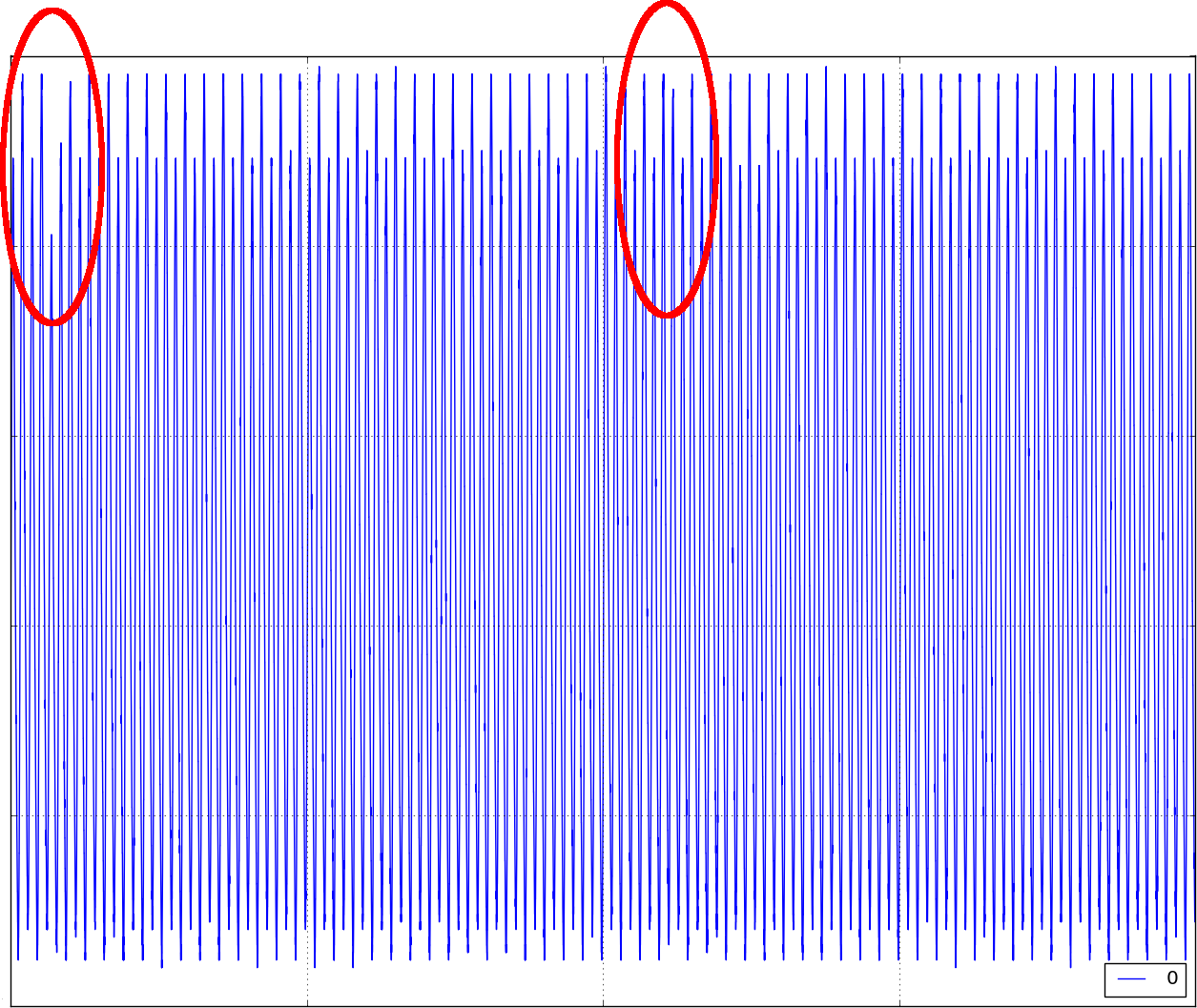
At a glance the graph on the scope will look like just a 125kHz sine wave. However, if you look closely at adjacent peaks of the sine wave you’ll notice that alternate peaks are lower/higher. This is the half frequency signal broadcast by the ID card. The phase of this signal (high then low vs. low then high) indicates a single bit of the data on the RFID card. The card will send the same bit for 32 periods of the carrier before it moves on to the next bit. (When it finishes all bits it resets to the first with no interruption).
Step through the peaks counting high/low/high/low until you find a double peak (high/low/low/high or low/high/high/low). This is where the card changed which bit it is broadcasting! See the circled double peaks on this sample reading. If you are patient enough, you can read the whole sequency by hand this way. However, it would be a lot more convenient to export data from the oscilloscope to a computer and have the computer do the boring work for you. We experimented with several systems for parsing ID bits from scope data automatically. Here is a script that uses a low pass filter and hysteresis to identify peaks and reads bits the same way I do it manually on the oscilloscope.
The ID card takes 57 ms to broadcast its data once (224 bits * 32 cycles/bit / 125kHz = 57ms). Ideally you want at least 16 points per cycle on the 125kHz carrier, which adds up to 115k readings (16 readings/cycle * 32 cycles/bit * 224 bits = 115k readings). Make sure you oscilloscope has enough memory for this and that you set it on the right time scale.
Cheap DIY RFID tokens
The reader transmits a 125kHz signal. The card/emulator has a coil and a capacitor connected in parallel with the same resonant frequency. The current induced in the card’s coil serves as both the power and the clock source for the card circuitry. The card’s circuitry can either be high impedance (allowing resonance) or low impedance (shorting out the coil). The card’s impedance slightly modifies the signal on the reader’s coil, allowing the card to send data to the reader. The card sends one bit to the reader every 2*k clock cycles. For either bit the card will alternate between high and low impedance each clock cycle; the bit determines which one comes first (this is called Binary Phase Shift Keying = BPSK). MIT ID cards send one bit every 32 clock cycles and send a total of 224 bits before they reset to the beginning of their data without interruption. To indicate the start of their data sequence, MIT IDs send 30 consecutive 0 bits (the first and last bit are both 1, and there seems to be an implicit requirement not to have 30+ of the same bit within the data sequence). From what we have seen, only 33 of the 224 bits vary between MIT ID cards.
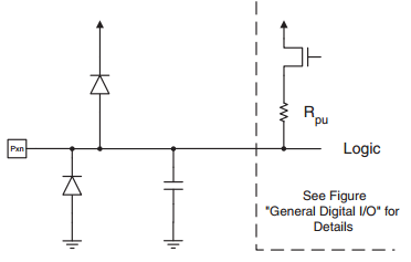
We created our own RFID tokens using an Attiny85 (general purpose 8 bit microcontrollers). We attach the resonant coil/capacitor across the two external clock pins (the chip is powered through its internal over-voltage protection mechanisms – see figure below). To send data, we either set them to output mode (shorting them to ground using internal transistors) or input mode (~30k pull-ups to Vcc). Since we only get one clock cycle per required output, most of our instructions set the mode of these pins. For 4 cycles out of every 32 used to send a bit, we break the protocol by doing a load-post-increment and a jump for control purposes. But it turns out to be ok to break protocol slightly because wireless protocols necessitate redundancy and error correction :D. Fancy code for outputting mostly-correct signals here, markdown file here.
Winding the coil
Update here is a nice website for calculating inducance/turns of various coil geometries. http://coil32.net/online-calculators/rectangular-multilayer-inductor-calculator.html
A coil can be wound around a cup and will probably consist of 50 to 100 turns. Generally speaking larger coils give better range/tolerance on location. The technical term for the donut shape is “multi-layer solenoid” and the inductance can be approximate using the following formula:
$L = \frac{0.8a^2 n^2}{6a + 9b + 10c}$
a = average radius, n = number of turns, b = length in direction of the axis of symmetry, c = width in direction of radius
For a donut, b ≈ c. All dimensions are in inches, the resulting inductance is in microhenries (μH).
I used ~350uH coils found that ~66 turns around a spice bottle or ~100 turns around my finger gave a reasonable inductance. For ease of removing the wound coil I recommend wrapping the winding surface with paper first – wrapped wire doesn’t even slide well off of spice bottles, never mind fingers.
Choosing capacitors
To achieve resonant frequency of f=125kHz with a coil of inductance L (in Henries), the capacitor needs to be have the following capacitance (in Farads):
$C = \frac{1}{4Lπ^2f^2}$
I chose C = 4.7nF, H = 350uH -> f = 124kHz -> within tolerance of components
Reading RFID cards with a microcontroler
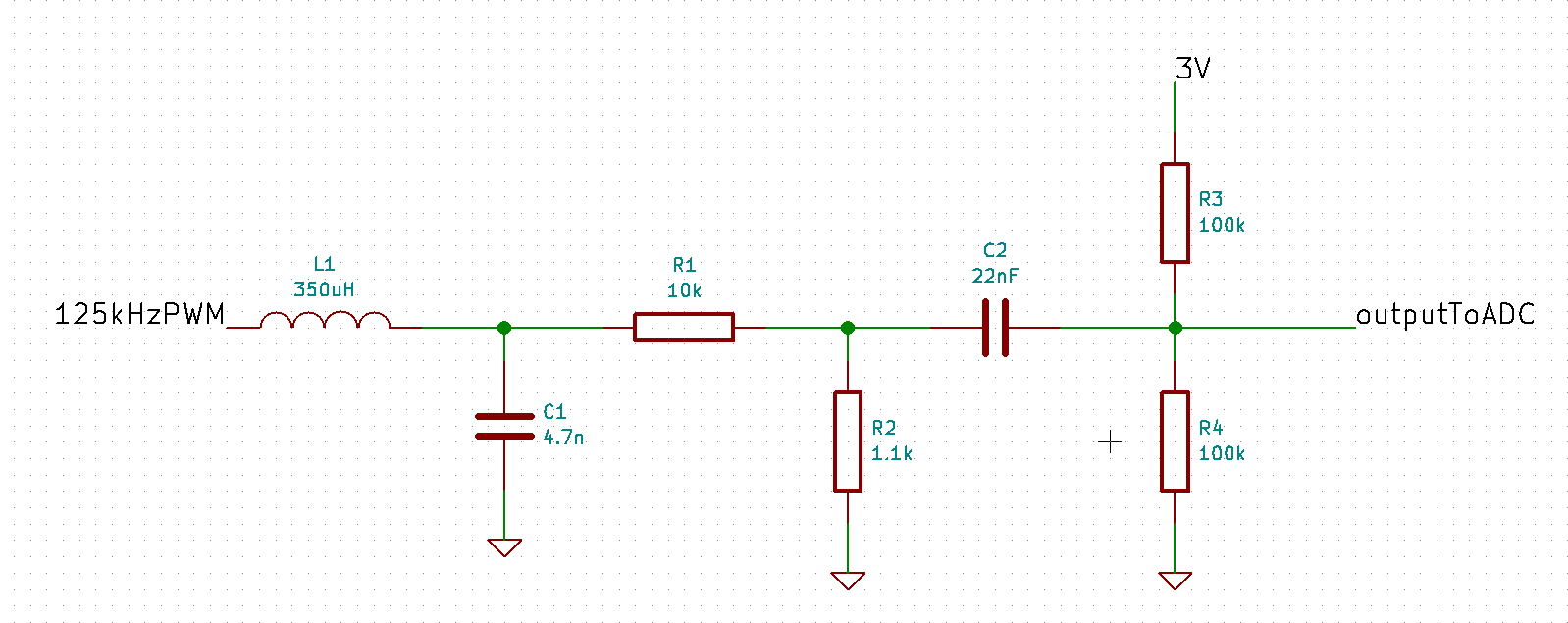
My microcontroler of choice is the STM32F4 Discovery (cheap dev boards!). It’s definitely overkill, but it came in nice packaging so whatever. It has a built in >1.4 MSPS (mega samples per second) 12 bit ADC and several LEDs for “user interface”. The simplest version of this reader only requires a resonant coil/capacitor pair and a couple other passive components.
The analog signal processing is [resonant coil/capcaitor] -> [resistor devider for scale] -> [high pass capacitor + resistor divider for offset] -> ADC. The rest is done digitally.
On the microcontroller there are a couple tasks running in parallel.
- PWM output (50% duty cycle) at 125kHz on a GPIO pin, driving the coil
- ADC sampling into a 1Ksample buffer, switches buffers and generates an interrupt when full
- ADC interrupt does signal processing on the most recently collected buffer (note that this must be faster than the next 1K buffer fills -> faster than real time, just at 1K samples lag)
The digital signal processing centers around a Phase Lock Loop (PLL) used to, well, track the phase of the ADC data. In a previous iteration we used the precise phase to try to demodulate the signal, but this turned out to be less effective than we’d hoped. The current algorithm just captures the maximum and minimum readings from each cycle. Over the 32 cycles spent transmitting one bit we calculalte ∑( − 1)n(maxi − mini). When the half-carrier signal is in phase this value is positive; when it is out of phase this value is negative. As we read bits we try to “sync” to the ID card (we are in sync if we have read enough of the same bit in a row). The reader stays in sync for the remainder of the length of the ID and write the bits it reads to memory.
Bulk ID collection
The same technology described above could be used at higher power to read at longer distances. It turns out that it takes much more power to read at longer distances, but it should still be possible to create a portable device that can read from about a foot away. This would make it easy to read IDs out of peoples pockets while walking by them in a hallway.
The most effective method of harvesting IDs would be to modify existing readers. Existing readers have a removable outer plastic casing covering the actual hardware. The plastic casing has plenty of extra room on the inside for someone to insert their own reader that records all cards tapped. This is most effective because in addition to copying card information you also learn one door that it (likely) opens.
Finally, we have theorized that setting up a booth that says “Please tap ID here” and provides some sort of acknowledgement as an incentive would work pretty well.
License
…what?